|
|
|
|
 Next I connected an electret (condenser) throat microphone directly to the radio input. Upon pressing the push to talk button, there was not sufficient microphone output amplitude to drive the transmitter.
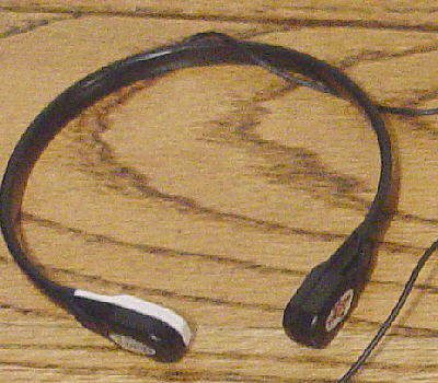
This is a new throat microphone that I have been using on my digital voice recorder. It has very good noise rejection, in fact, much better than the first one (Pryme} I used. It was purchased from Cabela's On Line Store where it was listed as: Fox Fire Throat Mic - Item: UE-226548 and Price: $29.99. It came with a push to talk button and an ear bud speaker. I removed the speaker and extra conductors and the connector plug. I mounted an 1/8 inch OD audio plug to the microphone leads so I could use it with the digital voice recorder. |
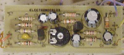 I searched the web for electret microphone preamplifier kits. I purchased two kits from Amazon Electronics, Inc. I assembled both and used the throat microphone on the input, and the ear bud speaker on the output. The one that seemed to work the best was the following:
|
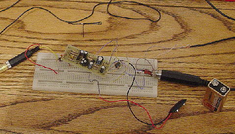 Using a proto board, the amplifier was connected to the microphone on the left, the radio on the right and the battery on the bottom. The push to talk button lead is not shown here.
First tests were disappointing in that squealing was back, so more radio frequency interference corrective actions were necessary. |
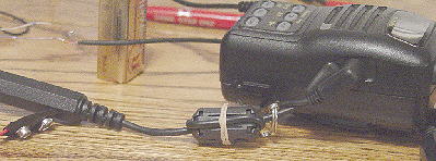
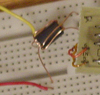 The solution was to place ferrite beads on the amplifier input and output leads. This is a bead taken from a junk box modem. It is cylindrical with six through holes close to the circumference. Ferrite is a non conductor so a single length of bare wire was threaded through three holes for each of the in or output terminals. This lowered the rfi level to the point that at amplifier maximum gain no squealing could be heard, although at this gain speech was clipped.
|
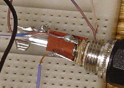 How does one determine which is the push to talk connection and which is the microphone input? The way I did it was to insert the male plug into the microphone socket. Then I turned on the radio and touched a wire to the largest diameter (ground) and to one of the other terminals. One of them will cause the transmit light to glow. In the case of the Yaesu, the male plug tip is push to talk and the next ring is the microphone conductor.
Also, male microphone plugs are not readily available. I found this one at Minute Man Electronics. Their site is not easy to navigate, but if you put "aircraft" into their search engine, it will get you to the plugs. |
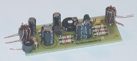 Mounted the rfi suppressors on the pc board. To the right is the input and to the left is the output. The single conductor is the positive lead for the nine volt battery.
A small amount of clear epoxy was used to bond the ferrite and wire assemblies to the pc board. The connecting wires were be soldered to the bare wire leads. |
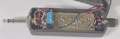 The plug and socket were mounted into the ends of a discarded ANR control and battery box. They were held in place with JB Weld. To reduce the space required the terminals on the plug were shortened.
Next a hole was drilled to slip the Push To Talk (PPT) switch wire into the bottom of the case. One coil of the stretch portion of the cord was fed through the hole and clear epoxy dripped onto the coil to hold it inside the case. The preamplifier pc board assembly was placed in-between the plug and socket with the board side up. To hold the pc board in place, pieces of wooden tooth picks were placed in-between the edges of the pc board and the inside of the case. Clear epoxy was dropped onto the mating surfaces to keep the tooth picks and the pc board permanently located. At this time the preamplifier input and output leads were connected. This was followed by connecting the nine volt battery leads. The negative lead was soldered to ground, and the positive lead to one side of the PPT switch. The other side of the PPT switch was connected to the positive side of the pc board and to the coil of a reed relay. The second coil lead was connected to ground. One of the relay contacts was connected to ground and the other was connected to the center lead on the plug on the left. The reed relay is the blue cylindrical object that is laying on top and to the left end of the pc board. Clear epoxy was dribbled over or dabbed on to attach and stabilize the leads and relay. |
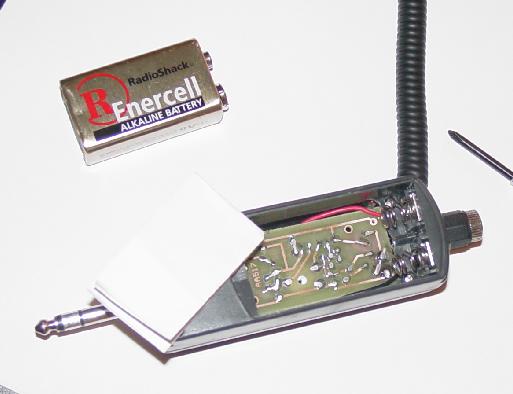 The back side of the case was installed. Originally, the case held two 1.5 volt AA batteries. The bottom of the battery box was removed to make room for the nine volt battery and both spring connectors were moved to right end. Four layers of paper were placed between the pc board and the battery to keep the battery from contacting the pc board.
|
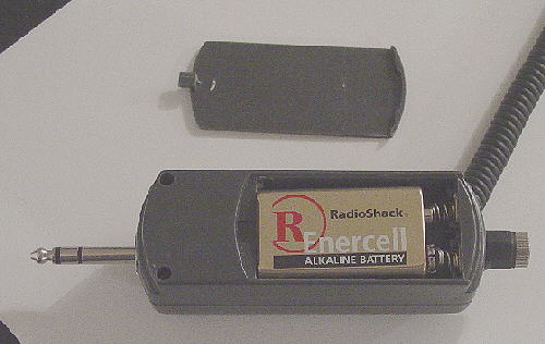 Battery in place and ready for closing the battery compartment.
A word about using the reed relay. I made several attempts to use a transistor switch. Not being good at electronics, I became frustrated with motor boating and more squealing. I tried the 12 volt reed relay and it worked. I checked the resistance of the coil and found it to be over 1k ohm. So when one presses the PTT switch, battery current draw is below five milliamp. So since the current only flows while transmitting, the battery should last for a year or more. |
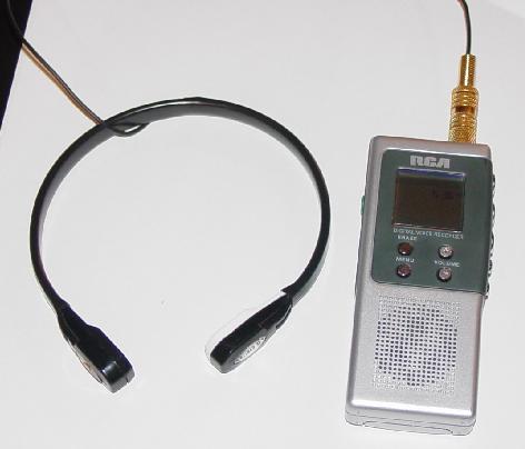 This system is made up of several components. On the right is an RCA RP5010 digital voice recorder. Plugged into the recorder is a throat microphone that contains an electret element.
I had tried noise canceling electret microphones mounted on a head set boom but with inconsistent results. Wind noise was always a problem. Then one day I put the mic boom down low against my throat and things were better, but not nearly good enough. Next time I flew I placed the microphone next my throat and covered it with a neck sock. I got a noise free voice recording. That was the day I started looking for throat microphones on the web. This setup works very well in that all wind, propeller, and engine noise is excluded. |
 I have been using a hand held Yaesu "Aviator Pro VXA-100" radio attached to my left leg as a means to listen for traffic when I leave, fly about or am close to, and return to an airport. Because of open cockpit wind noise, no one has ever been able to understand my voice transmission while flying. Every time I have tried to get a microphone to work, the output oscillates which is an indication of radio interference. I took the radio to the local electronics guru and he said it was a ground loop feed back problem with the radio. I called the company I purchased the radio from and described the problem. He said there was a fix and gave me another number to call. The recommended fix is to place a ferrite core radio frequency interference (rfi) suppressor or choke on the head phone cord as close to the head set as possible. (So if you are having a problem with a Yaesu hand held radio as described above, contact ALL POINTS, 12128 N. Division St. #160, Spokane, WA 99218-1905. Contact person is Harold Christensen at 877-255-7687. It will be sent free of charge.) These suppressors or chokes can be found on most cords that connect anything to a computer. I took an rfi suppressor off the radio 12 volt dc battery charging lead and mounted it on the microphone adapter lead. Then I wired the input to a ANR headset microphone lead, and found that I could hear myself squeal free in the original head set while transmitting.