|
|
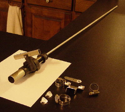 Changing hands to adjust flaperon position is uncomfortable, especially during the landing process. It would be desirable to remove flaperon displacement quickly after touch down, but this not a time to be changing hands on the stick. The mechanism shown is a continuously variable flaperon activation mechanism that was installed on the left side and below the seat. It is a modified gear rack and pinion crank extension section taken from a heavy duty camera tripod. 5/16 inch OD thick walled tubing was used to reach back to the swinging yoke that holds the "Tee" arm and aileron control torque tube. Total part weight as shown is 9.4 ounces.
|
 The 5/16 inch OD tubing was placed inside the slide tube. Spacers (lower right) were made from 1/2 x 1/2 inch aluminum angle. They hold the tube squarely against the inner slide wall. The original crank handle was discarded and replaced with a "Tee" handle made from a section of tripod leg.
The tripod slide length was cut to limit travel to 2.75 inches. All leg attachment points were cut away, and the down position covering tube was shortened so that it could be used to attach the assembly to the lower rear seat cross tube. |
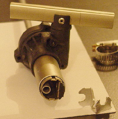
 This was the top side of the tripod. The small tube locator has been inserted, and two stainless steel pop rivets have been used to hold the tube and the slide stop in place. Both of these locators were fixed into place with JB Weld. It cannot be seen, but on the opposite side one stainless steel rivet was used to hold the stop and the gear rack to the sliding tube.
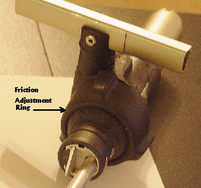
The round collar with the three axial ridges is a slide friction threaded adjustment ring. |
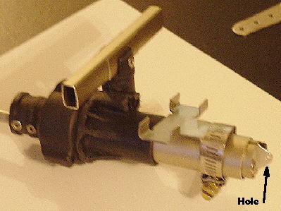 An attachment bracket was made from stainless steel and a hose clamp was used to clamp it to the bracket. This assembly will pass below the lower rear seat cross tube and two hose clamps will hold it to the tube.
To the far right one can see the 5/16 inch OD tube alignment bracket protruding from the slide tube. A cross hole was drilled through the protruding end to enable tying woven fish line which will be used to activate an on the panel flaperon position indicator. |
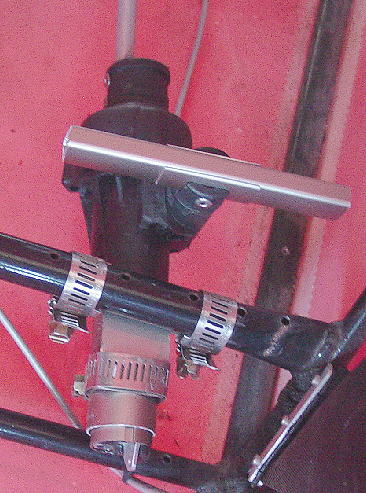 The new flaperon control installed in the FireFly and viewed looking to the rear and down while standing on the left side of the cockpit. Hose clamps hold the assembly to the lower rear seat cross tube which is no longer used for the seat. In this view the flaperons are fully deployed. The "Tee" handle rotates over and clears the cross tube.
This position was picked so that one can move the hand from the throttle and drop it into the gap between the sling seat and side of the fuselage to reach the "Tee" handle. |
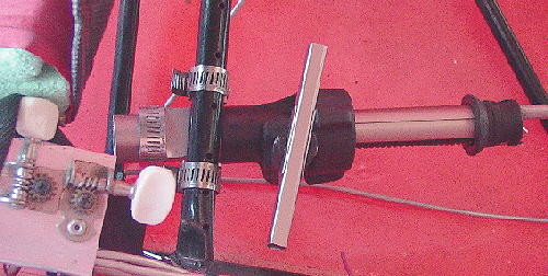 In this view the flaperons have been set to zero deflection.
|
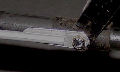 Tang on the left side of the yoke. The tang was fixed to the tube with three stainless steel pop rivets. In this view the flaperons were partially deployed.
I was worried that the friction adjustment ring may not be able to keep the slide from moving in flight. But one flight through rough turbulent air proved that the clamp had sufficient holding power. |
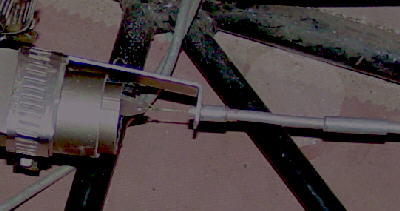
Photo shows the indicator guide tube mounting bracket in place and the fish line attached to the sliding tube. The guide tube runs up along the cage tube that ends at the upper longeron under the throttle attachment point. The tube continues under the upper longeron to the nose cone. Here it passes up over the upper longeron behind the left side of the nose cone and finally it passes through the panel from the back side. Plastic wire ties were used to fix the guide tube in place. |
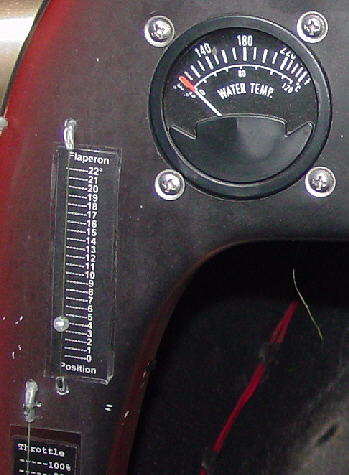 Microsoft Word was used to layout the flaperon panel indicator scale. Twenty-three degrees of flaperon movement translated into a displacement of 2.75 inches. The font pitch was increased until the scale length was exceeded, and then the line spacing was reduced until the printed scale matched the desired length. Then the words were added to the top and to the bottom, the background color changed to black and the font color to white, and the margins narrowed to prevent excessive black ink consumption.
To mount the scale, it was first trimmed to the desired size and the printed side was wall papered to the adhesive side of clear packaging tape. Then this assembly was stuck to the non-adhesive side of another piece of packaging tape. The excessive clear tape was trimmed away leaving a 1/16th of an inch border. This encapsulates and protects the scale from moisture that would cause the ink to run and to blur the scale. Also it provides an adhesive surface with which to attach the scale to the panel. This final assembly was slipped into position behind the bead and fish line and pressed onto the panel. To complete the indicator, the fish line is looped through a white bead two times and then was threaded through another guide tube passing through the panel surface. Here the fish line was tied to a spring whose opposite end is passed through a bracket which was pop riveted to the nose cone top and center. To properly calibrate the bead, it can be slipped up or down by hand. Bead/fish line friction is sufficient so the bead will not slip on the line when the flaperon position is adjusted. The original equipment removed assembly weight was 13.2 ounces including the de dent tube and the mounting bracket welded to the cage. The new system saved 3.8 ounces. Some of this weight was added back when the indicator was installed. |
Update - 07/07/05 |