|
|
|
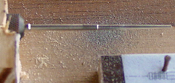
 The needle was placed in a Dermel tool chuck. When the needle is rotated at high speed the ink dot visually appears as a dark band around the needle. Using a small flat file the ink mark is removed. In this case the mark was placed at the 30% open position and material was removed to relieve the needle from the 30% to 40% positions.
|
 After each stroke of the file, the motor was stopped and the OD measured until the OD was found to be 0.075 inches (OD at 40% position). The lip was feathered so that the needle would not catch on the jet as it was moved up and down.
|
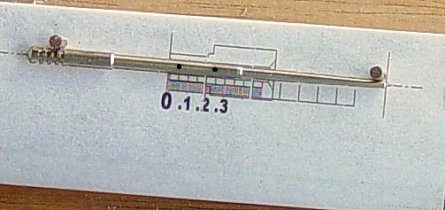 After a test flight, the needle was turned to the set up block and an ink dot was placed at 5% and another at 25%. Then material was removed from between these positions.
 It is important to keep a log as the work is being done. Record the throttle position from which the material is to be removed. Then using a micrometer, measure and record the OD in that area. Next remove material. Put the needle back in the gauge and re-ink the same position. Measure and record the OD in the area where material was removed. Test fly the needle. If needed and based on EGT and throttle position, pick the next area for material removal. The trick is to not remove too much material before taking a test flight to see if you are getting the desired effect. If one removes too much material the needle can be salvaged by reducing a needle jet size. |
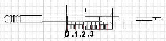
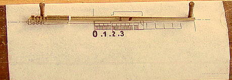 Using CAD software, relative throttle position was superimposed onto the needle and needle jet image. A full-scale print out was fixed to a piece of wood and covered with clear packaging tape. One locating nail was driven in next to the first slot from the bottom. A second locating nail was driven in on the same side and close to the end of the needle. These two nails let one accurately reposition the needle over the drawing. The black ink dot on the needle is located at the 30% and 40% open mark.