|
|
|
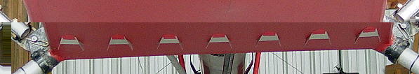
The FireFly fuselage shape contour is made of up of flat planes that meet with abrupt corners. This makes the fuselage easy to fabricate, but it is not conducive to low drag airflow. Part 103 specifies certain widths etc to be sure that the design presents sufficient drag to meet ultra light vehicle design criteria. But nothing is said in Part 103 that limits installation of devices to enhance air flow about such dragy fuselage components. Vortex generators were installed on the bottom and sides of the fuselage help the air flow better around the fuselage and through the propeller. |
|
|
|
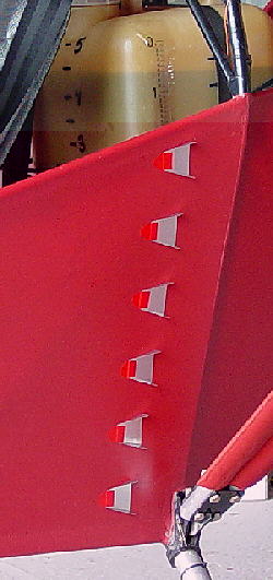 The best vortex generator position would be to place them closer to the break in plane or edges.
On the bottom, the orientation was to place them to face straight ahead. On the fuselage side things were a little more complicated. I raised the tail until the wing angle of attack was six degrees (cruise angle of attack??). Then the vortex generator was prepared with double sided adhesive tape. Next, it was placed on a incline meter and rotated to fifteen degrees. The whole assembly was held up to the fuselage and the vortex generator slid off the incline meter and stuck to the fabric. |