|
|
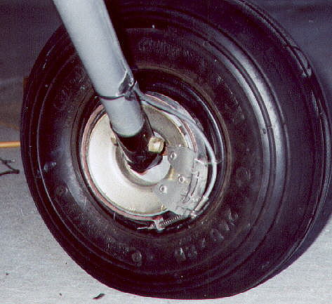 The brake cable is fed down inside the small aluminum tube on the back side of the landing rear leg. It passes through the floating piece, and the tubing ends in a bicycle cable guide that is stepped down in size. This step is what takes the reaction between the cable, the guide tube and the reaction plate and holds one end of the brake band. The cable passes through a compression spring that unloads the brake band and ensures that the one end of the band stays in place on the cable guide. Next the cable passes through a hole in the other end of the band and two cable stops.
|
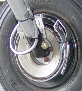
 Later I realized that putting a small aluminum tube through a hole in thin stainless steel was not a good idea. I drilled out the hole and placed a spacer over the aluminum tubing and in the hole. This spacer provides vibration wear resistance to the tube.
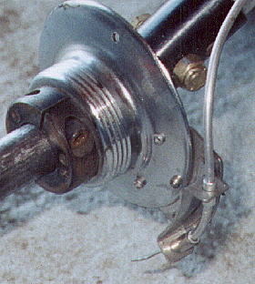
I discovered that the small aluminum cable guide tube, shown on the left, was not strong enough to with stand the compressive reaction loads while applying the brakes. The small tubing section between the two protective and locating supports actually crumpled due to strong application of the brakes. |
 To give additional support, the small diameter cable guide tube was slipped into another larger diameter tube, and the set of tubes bent to the desired shape. The smaller tube length was shorter so that a socket was formed to accept the cable guide tubing on the back side of the landing gear leg.
The following diagram better explains how the brakes work. Replacing the leather bands with high coefficient braking material greatly reduced the force required to activate the brakes and to hold the FireFly during warmup and taxiing. Additional support had to be given to each end ot the band to keep from deforming the band ends. |
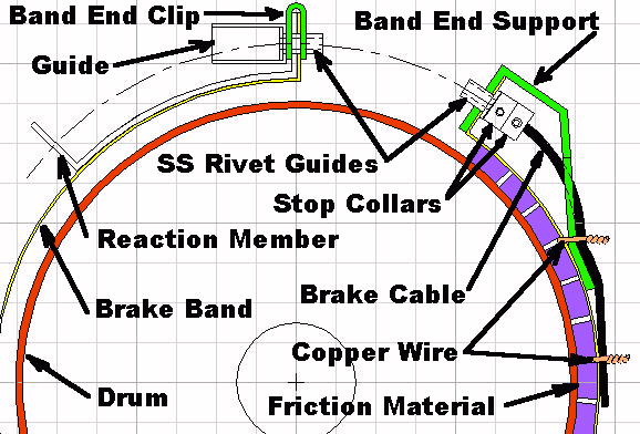
The band end clip prevents the band from sliding off the locating sleeve when one is dragging the FireFly backwards into the hangar. One-eighth inch OD stainless steel rivets were used as cable feeds and locator sleeves. The rivet head on the left was ground until it would slide into the a bicycle cable locator end. The rivet length is quite long so the compression spring that unloads the band could locate over them. The band end support on the right keeps the band end from deforming under load. Another rivet was used for a guide and to locate parts and the compression spring. Copper wire twist ties were used to hold the support free end and the excess cable out of the way. Two cable stops are used to terminate the brake cable. Although it is not shown on the diagram, small diameter Tygon tubing covers the excess brake cable. |