|
|
|
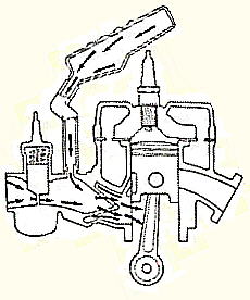
Or - Stopping Cold Weather Slobber Since mounting the Victor 1+, I have discovered the same problem as experienced with the Rotax 447 in that, as one slows the engine to a certain point, the fuel flow begins to increase instead of decrease with further throttle closing. Someone on the Kolb E-mail List mentioned that rotary vane flow meters will give false readings due to pulsations that cause the vanes to oscillate at the low flow rates. With the current set up this is possible, because I have used flexible tubing from the tank to the pump. To save weight, I replaced the flexible hose with aluminum tubing between the fuel pump and the flow meter. I thought this would stop all volume change experienced by the fuel flow between the two. I tied the fuel flow sensor to a cage cross member, and I experienced higher readings than ever before. This seems to indicate that the sensor is more sensitive to mechanical vibration than to fuel flow pulsations, and it should be soft mounted. Due to the fact that the engine(s) are tuned to run and develop their power at the higher rpms, most manufacturers are not concerned about how their engine runs at/or below 4,000 rpm. But one spends quite a bit of time during engine warm up, decent from altitude and taxiing to and from the runway. When you are limited to five gallon tank capacity, it seems a waste to burn almost a quart of fuel during these activities per single flight. Also, if one can lean out the engine at the lower speeds, engine warm-up will be quicker, and the engine will run warmer at idle. This will reduce the risk of cold seizure during take off and long descents. There are several reasons for the air/fuel flow to become richer as the throttle is closed. 1) Induction system imbalance/tuning. As the throttle is lowered to a position below the power band, induction system imbalance starts to effect the fuel/air ratio. It has to do with induction system tuning. When the piston port or reeds close at the slower engine rpm, the flow energy in the intake manifold turns into pressure as the flow stops. Then the pressure starts to decrease due to a flow reversal back toward the carburetor venturi. If the rpm become low enough, the flow will reverse through the venturi and pass back fuel and air out to inside the air cleaner volume. On the way out through the venturi, more fuel is added to the original mixture. Finally the induction port or reed opens and the flow is reversed again, but now in the correct direction. The pass back air and fuel pick up additional fuel as they pass through the venturi and heads for the induction port followed by some fresh mix air and fuel. The port or reed closes and the whole process repeats. This may explain why the fuel flow rate increases as the engine speed falls below 4,000 rpm. 2) Worn induction system valving. As the engine slows more and more of the fuel/air volume being compressed in the crankcase will escape past the valving back into the intake manifold. This will have the same effect as 1). 3) Liquid fuel takes up heat and vaporizes in side the intake manifold while the induction port or reed valves are closed. This will increase the fuel/air pressure inside the intake manifold and cause fuel/air reversal through the venturi too. Since the Rotax 447 and Victor 1+ were/are low time engines, I believe 2) can be discounted. But the combination of 1) & 3) may explain why gasoline will drip from the air cleaner when the engine is running at idle speeds in cold weather, and to load up the engine at low rpms. |
|||||
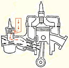
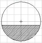
 To improve low end throttle response, scale aircraft engines, snowmobiles, ATV's, and motorcycles use "boost(er) bottles" and Yamaha came up with the "Yamaha Energy Induction System". It seems that such a system could be developed for the Rotax 447 and Victor 1+ that would improve low rpm performance/economy. The "rule of thumb" is that the volume of the bottle is equal to the cylinder displacement and the connecting hose diameter is .3 to .5 of the carburetor throat diameter. In the case of the Rotax 447 and Victor 1+ where the carburetors are much oversized, it may be possible to get by with much smaller dimensions.
The Figure seen on the left and the "rule of thumb" info came from the above source. |
|||||
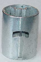
 I wanted to try out a booster bottle on the Victor 1+. A carburetor to intake manifold extension was not considered because it may unfavorably change other desirable engine characteristics and increase weight. So the easiest thing to do was to modify the Bing carburetor. Upon closing the throttle, the Victor 1+ fuel flow rate starts to show an increase at about twenty percent throttle. So the desired effect is necessary only during the first/last twenty percent of the throttle opening/closing. I wanted to try out a booster bottle on the Victor 1+. A carburetor to intake manifold extension was not considered because it may unfavorably change other desirable engine characteristics and increase weight. So the easiest thing to do was to modify the Bing carburetor. Upon closing the throttle, the Victor 1+ fuel flow rate starts to show an increase at about twenty percent throttle. So the desired effect is necessary only during the first/last twenty percent of the throttle opening/closing.
By opening up the sliding throttle valve to the intake manifold one can gain about 100 cc of volume. Also, by suitable port position, the effect can be restricted to the throttle opening of zero to 20%. To add additional volume, a hole can be drilled through the carburetor body so that an external 300 cc booster bottle can be added. |
|||||
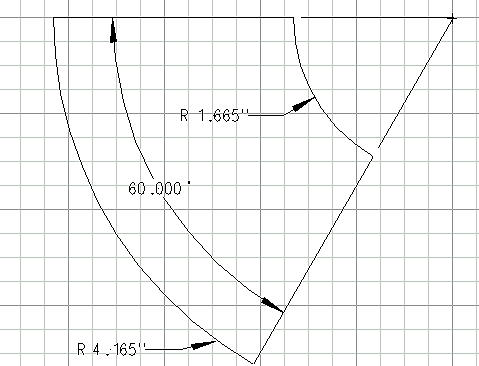
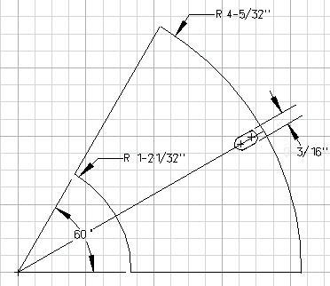
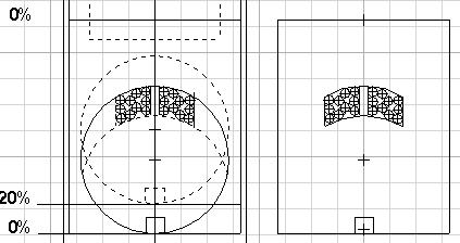 A CAD sketch was made so that the bottle opening port would be fully open with the throttle closed and entirely closed at 20% throttle opening. Port area was selected to be the same as for a 1/2 inch ID tube. This gives a connecting hose to throat diameter ratio of 0.35. Additional material can be removed by continuing the two arcs to the point of intersection. If this is done, the ratio will rise to 0.48. These values fall inside the "rule of thumb" values of .3 to .5 cited above. A CAD sketch was made so that the bottle opening port would be fully open with the throttle closed and entirely closed at 20% throttle opening. Port area was selected to be the same as for a 1/2 inch ID tube. This gives a connecting hose to throat diameter ratio of 0.35. Additional material can be removed by continuing the two arcs to the point of intersection. If this is done, the ratio will rise to 0.48. These values fall inside the "rule of thumb" values of .3 to .5 cited above.
The template was cut and glued to the sliding throttle valve. The 1/8 inch OD drill centers were punched and the holes drilled. Small files were used to remove the excess material. |
|||||
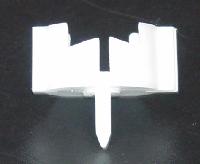
 The spline that guides the needle and clip retainer was not cut, but it was rounded to encourage smooth flow around it.
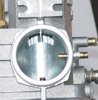
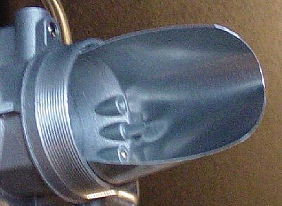
Oil and fuel passing in through the port and falling to the bottom of the slide valve are not trapped but can return into the venturi throat by way of lower slide surface drain holes. These drain holes can be seen in a photo below. |
|||||
 The plastic needle and clip, and return spring retainer was modified to enable a clear flow area. Since the inside of the throttle slide valve and the volume above it will act as the booster bottle, it is important to minimize outside air leakage. Clearance between the throttle cable OD and the bore ID was shimmed with brass tubing.
|
|||||
|
Replaced throttle valve cylinder and plastic spring retainer, and started the engine. The engine speed was much higher that normal idle. Shut the engine down. Backed out the screw that adjusts the throttle valve idle position, and restarted the engine. The lowest idle speed was 2,300 rpm. Fuel flow rate was .4 - .5 gph and no dripping of fuel from the air cleaner. Returned the original parts to the carburetor, and started the engine. Fuel flow rate was 1.5 - 1.7 gph, and fuel dripped from the air cleaner. This looks promising, in that, 100 cc of booster bottle volume made a large fuel flow rate change without an increase in overall weight. If I can get the idle down, there is no need to add additional external bottle volume and its corresponding weight. |
|||||
|
One is faced with two alternatives. 1) Plug the holes and accept the increased difficulty associated with needle adjustment. 2)Accept the leakage and reduce the little square cut out area in the induction side of the slide valve. This is more favorable as it does not interfere with needle position adjustment. |
|||||
|
If needed, a new slot will be filed into the brass. Slot area adjustments will continue until the Victor 1+ idle speed range is normal.
|
|||||
|
Repeated previous test with the latest modifications. Basically the same result on idle speed, which indicates the intake manifold vacuum is floating the throttle valve against the return spring. EGT was about 1,000 degrees F. at 2,300 rpm. This is the highest EGT I have ever seen at this speed, and it was confirmed by the lowest reading I have ever seen on the fuel flow meter. To get more spring return force, I have ordered some springs from Century Spring Corp. which will replace or nest with the original throttle valve return spring. No dribble on the wing after idling the engine. 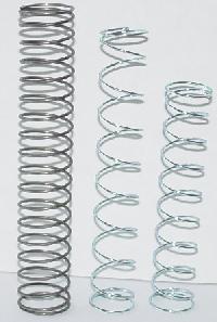
The original spring is shown on the left. The other two were made by Century Spring Corp. Stock # C-756, 23/32 inches OD, 3.5 inches long and made from .041 OD wire. The middle spring has been stretched. One of the new springs will be placed/nested inside the original spring. Hopefully this will increase the throttle closing force so that intake manifold vacuum will not lift the valve and will let the engine idle at 1,000 rpm.
|
|||||
|
Two tests were run to see if there would be a true shift in EGT's at the lower engine rpm. The tests were run two days apart. Air temps were within two degrees of each other, and the barometer read a little higher for the second (unmodified throttle valve) test. The average increase in EGT by using the modified throttle valve was 71 degrees F. The nested throttle return spring system was able to keep the modified throttle closed, and the lowest rpm attained was 1,850. All EGT readings were to the nearest mark on the gage.
These data indicate that the 100 cc internal booster bottle is leaning out the engine at the lower rpm. It would be interesting to make a carburetor to intake manifold extension through which and external booster bottle could be attached, and to repeat the testing to see if one would be able to get the same results with an unmodified carburetor. But the weather is warming, and it is time to get the FireFly into the air, so this effort will have to wait. |
|||||
|
Another condition should have been listed earlier. 4) At idle speeds below 2,000 rpm engine rotational shaking in the engine mounts may cause the fairly heavy closed throttle slide valve to bounce up against the return spring. If this is the case, the needle is lifted too and there is a strong possibility that fuel is being sloshed or pumped into the venturi. |
|||||
|
It appears that two independent phenomena were at work. 1) Intake manifold de-tuning causes higher fuel consumption at engine speeds below 4,000 rpm. 2) At engine speeds below 2,000 rpm, a weak throttle valve spring lets the throttle valve and needle valve vibrate up and down pumping fuel into the venturi. I believe what happens is that as the needle is bounced up additional fuel flows into the float bowl to make for the lost volume. Then the throttle and the needle come back down against the stop. This causes a local increase in fuel level in the main jet percolation area which greatly enriches the air/fuel mixture that is passing up between the needle and the jet. Basically, the vibrating needle and throttle slide in combination with the float valve act as a pump, and pumps fuel into the venturi. |
|||||
|
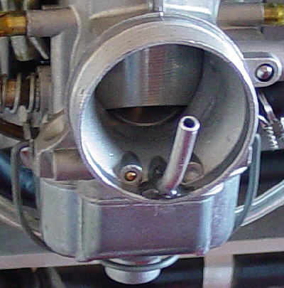 When you believe you have something fixed, you find that it is not. The double springing of the throttle slide valve was not a fix. I have found that the Bing carburetor occasionally dribbles on the wing at engine shut down. To be sure that the fuel dribble is caused by a de-tuned (short) intake manifold, I inserted a 3/16 OD aluminum tube into the idle and percolation jet air source vent. I bent the tube up so that it would not be possible for fuel to be expelled from the vent due to excessive vibration.
|
|||||
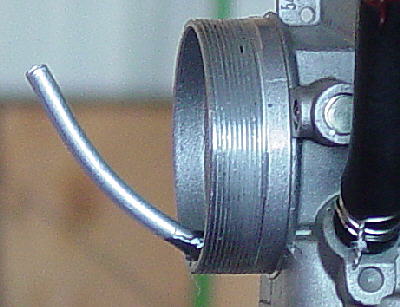 A test flight proved that the tube did not interfere with engine operation, but upon landing, taxi back and engine shut down, the carburetor dribbled fuel. This provides more evidence that the problem is an intake manifold tuning problem. At this point it seems that the only cure will be a booster bottle.
|
|||||
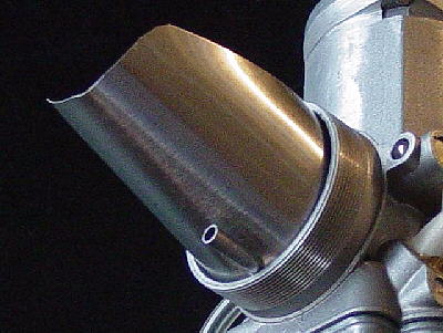
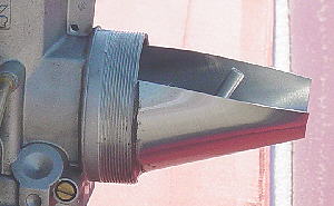 With the return of cold weather, the Bing carburetor is starting to dribble fuel and oil from the air cleaner onto the wing and everything else down wind from the propeller. I installed a carburetor inlet bib. The idea is to slope it upward so that as the liquid gas/oil fly out under the throttle slide the heavy liquid particles can not accelerate upwards and instead impact on the bib surface. The slope is high enough so that the liquid will flow down the bib surface and be sucked back into the carburetor before it can spill or fall on the inside of the air filter.
|
|||||
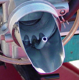 The bib is cone shaped and cut from aluminum house flashing. After cutting the proper shape, the flat sheet is rolled and formed over a 3/4 inch OD tube, so that the end that goes into the carburetor ID holds the cone in place by springing outward. After the bib is shaped, a notch is cut out so that it fitted around the bottom of the percolation vent tube. The inside of the carburetor inlet and the bib were cleaned with lacquer thinner. JBWeld was used to fix and seal the bib in place. The air cleaner filter was replaced. After a test flight and a long taxi back to the hangar at lower than normal engine speed, there was no dribble on the wing.
If I had not installed the aluminum vent tube, the liquid impacting onto the bib surface could run down the bib and into the vent hole. I am not sure this would be a good thing. In my case it has to build up until it can flow into and through the carburetor throat. This means that on taxi out to the runway and at first engine run up the liquid stored in the bib will be sucked into the carburetor inlet causing the engine to run a little rough for a few seconds. |
|||||
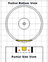
 For those of you have a dribble problem, here is a sketch of the pattern used to make the bib for a Bing 36mm carburetor. This size was selected so that it would fit nicely inside the air filter without restricting carburetor air flow and no risk of the bib passing into the carburetor if it comes loose. To further safety the bib, one could align the vent tube with the bib surface and run a safety wire around the tube and through two holes at the outer end of the bib.
If I had it to do over again, I would run the percolation vent tube under the bib and keep it as short as possible. This would save a little weight. |
|||||
 I re-worked the design so that the percolation vent tube would come out from the bottom side of the bib.
Two 3/16 OD holes are drilled next to each other on the cone center line leaving about 1/16th of an inch material on the edge. The remaining material is removed with a small file. As before, the blank is rolled into shape over a small diameter tube so that it fits into the carburetor mouth with sufficient spring back to hold it in place. |
|||||
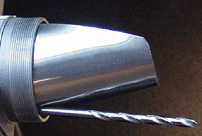 After the bib was temporarily put into place, a 3/16 OD drill bit shank was inserted into the slot, and the metal worked and bent until the shank would slide into the percolation air hole.
|
|||||
 This shows the metal deformation caused by working the metal with the drill bit. The small tube is 3/16 of an inch OD and will be used to extend the percolation hole through the bib.
By bringing the tube through the bib, it helps to stabilize the bib. The bib and tube weighs less than five grams. |
|||||
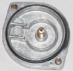
 The assembled bib viewed from above. No JB Weld has been applied to hold it together.
One can see the small tube that passes through the bib and into the percolation air vent. The bib, tube and carburetor throat will be cleaned with lacquer thinner. JB Weld will be used on the connecting edges to seal the tube and the bib to the carburetor. |
|||||
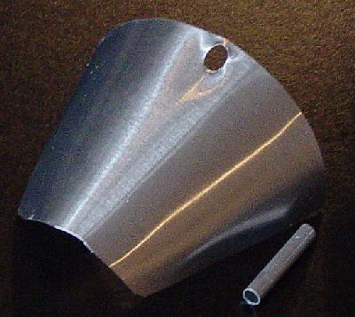
 The assembled bib viewed from below. No JB Weld has been applied to hold it together.
The outer edge of the cone was trimmed to make it square and then the sharp corners were rounded to prevent them from damaging the filter material while mounting the air filter.
When the weather warms, this bib will be installed on the Victor 1+ carburetor.
|
|||||
|
|
|||||
|
If you would like to see these changes, click here. This leads me to believe that one may be able to overcome this problem by "Teeing" the carburetor vents together and moving the float bowl static reference point away from the unstable air surrounding the engine to down below the wing, where the air pressure is fairly constant. I have not tried this, but it may be a solution. If so, it would be much easier than making a bib. |
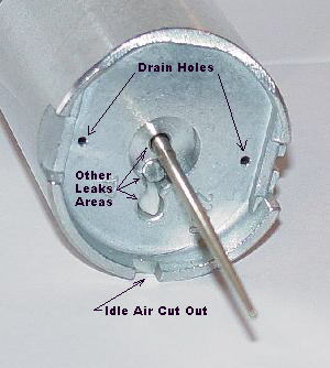 At first I thought that new idle jets were the answer. But upon studying the way the idle system works, it became apparent that the root cause of the high idle rpm was air leakage through the various holes in the bottom of the slide valve with the throttle closed.
 To block the throttle valve idle air cut out, a slot was cut vertically just in front of the cut out. A 32 tooth hack saw blade was used and the slot was made 1/4 of an inch deep. A brass plate .025 inches thick by .25 inches wide was cut to fit lengthwise in the slot. The surfaces of the brass were roughened and JBWeld was used to hold the brass in the slot. Two small holes were drilled so that copper wire rivets could be used to further safety the brass plate in place.
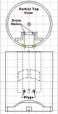 Fuel and oil did find its way into a small volume in the throttle slide valve that is not ported to the venturi or to the spring chamber. This was corrected by drilling two holes from the front of the slide through and just above the bottom surface of the small volume and into the spring chamber. The drill hole entrances were tapped to 4-40 Thd and sealed with a JBWeld in and on the threads of a short piece of a brass screw.
 Also, since the 36mm Bing is greatly oversized for the Rotax 447 and the Victor 1+. Both engines will develop full load rpm at less than 40% open throttle. At this throttle position, the venturi throat has an open area of 0.588 square inches.