|
|
 Since cutting the power tips and adding the third blade to propeller, I have noticed some play in the belt reduction unit. Simonini does not like extensions and would like the propeller balanced to one gram or less. I have been careful to measure the individual blades and to keep them the same, but this assumes all blades are exactly a like. This may not be the case, and so, I decided to check the static balance of the complete propeller assembly. This was done by suspending the propeller on a string through its rotational center and supported by a bracket attached to the garage ceiling.
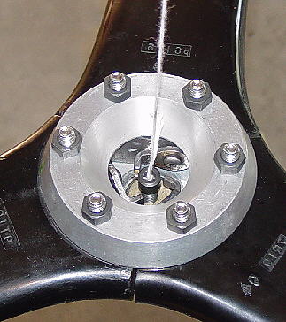
To position the string through the rotational center, a socket head cap screw was inserted in the spinner attachment hole in the IVO pitch adjustment bolt. A hole was drilled crosswise through the top of a socket head cap screw and a pin made from a pop rivet mandrel was slid into the hole and acted as a pivot for the string. (A hole drilled along the center bolt axis would have been much better, but I do not have a lathe.) Each time a balance reading was to be taken one had to check to be sure the string loop was centered in the middle. The advantage of this scheme is that one can raise or lower the string attachment point relative to the propeller center of mass. As one raises it, the system becomes less balance sensitive. It lets you rough balance. Then as one lowers the attachment point the system becomes more and more sensitive and shows greater vertical tip deflections for the same amount of imbalance. The adjusting is done by rotating the socket head cap screw and/or the IVO pitch adjustment bolt. |
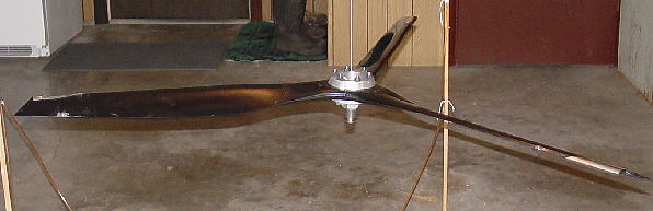 In the garage with the doors and windows closed to prevent air currents from disturbing the propeller. This is a rough balance. There is a dime resting on the outer most portion of the left blade. I had set up a three position water level so that I could check all blades at one time, but this proved to be impractical. All that is needed is a vertical scale in one position just beyond the radius of the propeller tips. When balance readings need to be taken, bump the outer tip of the propeller blade so that it will slowly rotate all blades past the scale in a horizontal plane.
|
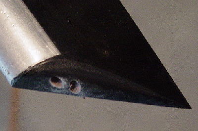 My first thought was to drill and remove material from the heaviest (down/lower) blade. These are two one-eight diameter holes that are two inches deep. It was not very productive because I was drilling into low density foam material.
|
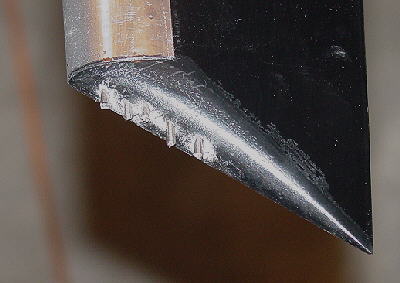 Next I moved to the lightest (up/higher) blade. I drilled small holes about one inch deep into the end of the blade and inserted pieces of pop rivet mandrels into them. After each hole was drilled and mandrel inserted, balance was rechecked. As you can see, it took five mandrels to do the job. The third blade required only one hole and one mandrel.
|
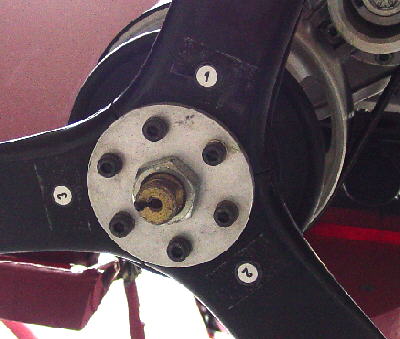 After balance had been achieved, the mandrels were removed one at a time, coated with JB Weld and re-inserted into the holes. A pin punch and hammer were used to drive them in flush with the blade surface. All open holes were epoxied shut and all surfaces contoured to their original shape. To prevent mixing blade positions, the blades were individually numbered.
Remounted the propeller and flew for a half hour. It seems to be smoother than before but it is difficult to be sure. Time required to check and re-balance was one afternoon. Is the balance better than before? Yes! |