|
|
|
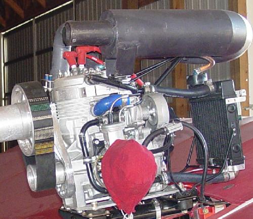
I had a cooling system failure and lost most of the coolant and overheated the Victor 1+. The following modifications were made to increase cooling system reliability, make it easier to refill and check coolant level, and to remove some weight from the cylinder water jacket clamp that is a major support for the exhaust pipe and muffler.
|
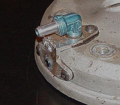
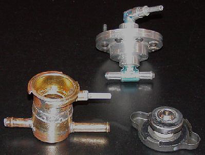 The original coolant system pressure release (shown in the back ground) is being replaced by a small expansion tank with a pressure release cap. The small line from the neck will go to the suck back bottle. The bottom two connections connect to the burp line between the head and the top radiator tank connection. A restrictor has been placed in the short connector to minimize fluid flow through the burp line to the radiator, but it still allows air to escape from the upper radiator tank. The new system weighs .2 ounces more than the old system, and it lets one easily top off the coolant. The expansion tank was made from three small brass radiator cap necks.
|
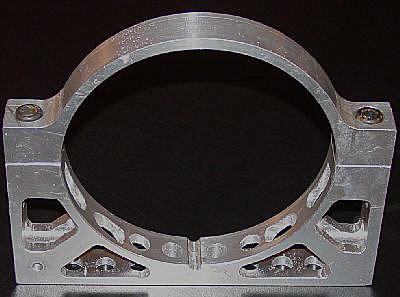 The original cylinder water jacket clamp to hold the muffler and exhaust pipe was a solid piece of aluminum. Since the engine was down for repair, it was a good time to remove excess weight from the clamp.
|
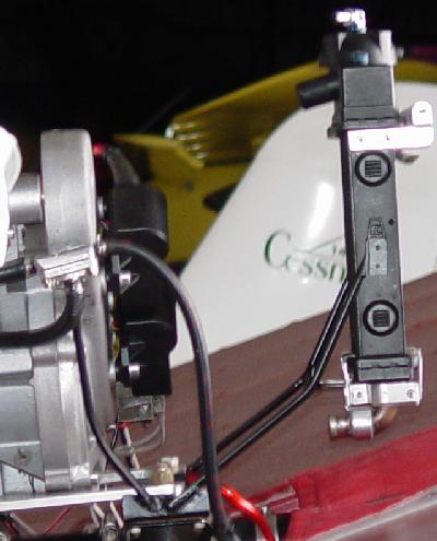 Side view of radiator setting in the new mount made of thin wall steel tubing that attaches to the cage portion of the engine mount. Two pads are welded to a cross tube and these pads support and locate the lower radiator tank. Two pop rivets on each side will hold the radiator in place.
A second tube was welded to the rear right side cage attachment pad to provide a fuel pump support. |
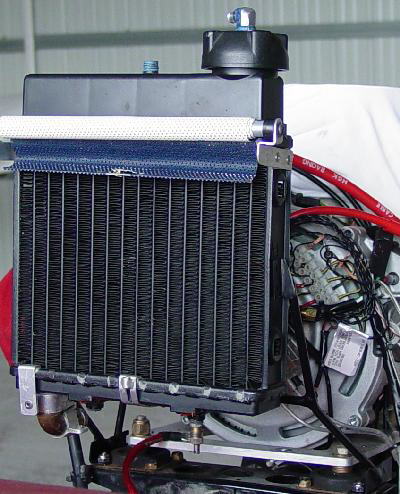 The front view of the radiator setting in the mount.
The rub rails for the shutter have been removed. They were made out of steel umbrella bows, and I found that the difference in metal temperature expansion rate (aluminum radiator core) was too high. One came loose and passed through the prop. |
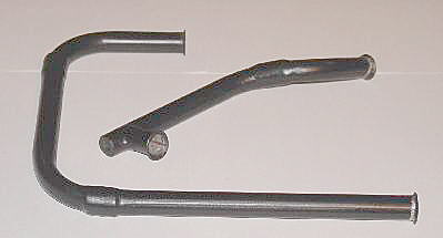 Rigid coolant tubes were fabricated out of a gas furnace heat exchanger tubes. They were "U" shaped and this let me cut and butt weld the tubes to give the desired shapes. The reason for the bumps is that I am a neophyte welder and so I filed the welds smooth, and lap welded another layer of tubing material over the the original weld.
|
 The short tube goes forward from the head to the upper radiator hose. The short end with the small hole contains threads to mount the coolant temperature sensor. Hopefully, this mounting of the temperature sensor will reduce the shock and vibration seen by the sensor. The longer tube connects to the water pump, passes back over then down and back forward under the engine reed valve assembly to connect to the lower radiator hose.
|
 The head temperture sensor mounting hole was plugged. The shock and vibration is too intense, and it killed two temperature sensors. The sensor is going to be moved to the coolant return tube to the radiator.